When designing and assembling PCBs, the acronyms SMT and SMD are often used interchangeably, causing confusion. However, while related, SMT and SMD refer to distinct aspects of the PCB production process.
For PCB assemblers and designers, accurately understanding the difference between SMT and SMD is important. Confusing these terms can lead to errors during component sourcing, documentation, and assembly if expectations are misaligned between teams.
In this article, we’ll clearly define SMT and SMD, explain their unique meanings in relation to PCB manufacturing, discuss why distinguishing between them matters, and provide tips for optimizing your SMT assembly process. Grasping the key differences will equip you to efficiently source components, communicate specifications, and work with assembly partners.
With this introduction, the intent is to:
- Establish the problem of SMT/SMD confusion upfront
- Emphasize why understanding the difference is important
- Provide an overview of topics covered
- Use clear, benefit-driven language for the reader
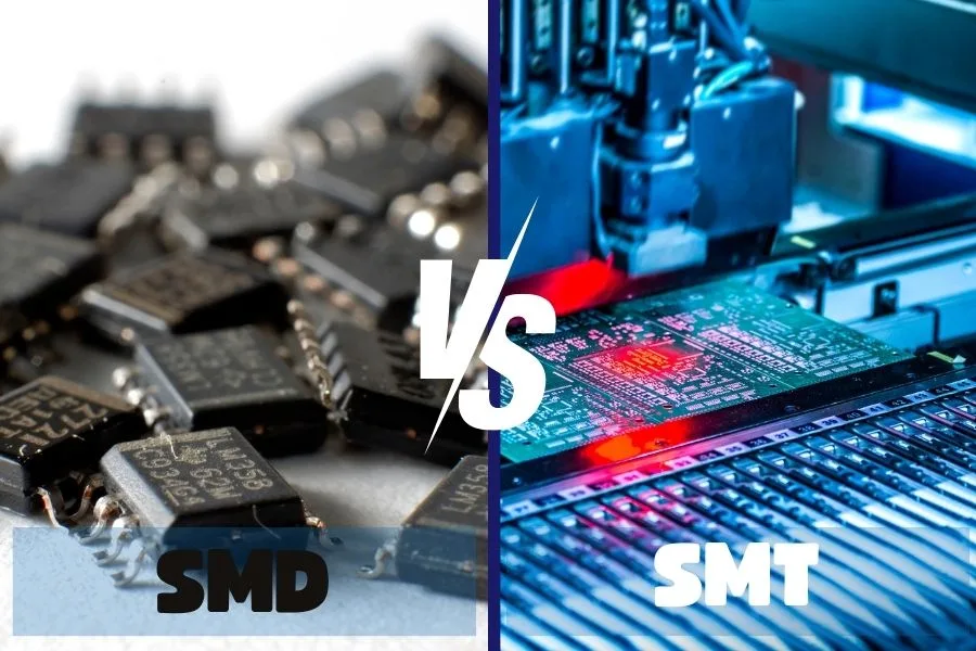
What is SMT? Defining Surface Mount Technology
SMT refers to theoverall assembly process of mounting electronic components directly onto the surface of PCBs without through-holes. In an SMT process, components are placed onto conductive pads on the board surface and soldered into place, usually by automated pick-and-place assembly machines.
Some key advantages of SMT include:
– Higher component density – More components can be packed onto a PCB surface vs using through-hole placement.
– Component miniaturization – SMT allows very small component sizes not feasible with through-hole assembly.
– Automated assembly – SMT is optimized for automated pick-and-place machine population.
– Reduced labor – Automation means less manual soldering and assembly effort.
– Multi-sided assemblies – SMT allows components to be placed on both sides of a PCB easily.
– Improved electrical performance – Shorter traces and connections enable better high-frequency operation.
Common SMT component types include quad flat packs (QFP), ball grid arrays (BGA), chip resistors and capacitors, and small outline integrated circuits (SOIC). These component packages are designed without leads specifically for surface mounting.

What Are SMDs? Explaining Surface Mount Devices
SMD refers specifically to the electronic components that are designed for SMT assembly and mounting. SMDs are packaged without leads or pins, optimized for direct soldering onto PCB surface pads.
Some common examples of SMD component types include:
- 0201 and 0402 Chips – Tiny chip resistors, capacitors, transistors in 0201 or 0402 sizes.
- QFP – Quad Flat Packages with leads on all four sides. Range from 20 pins to over 300.
- SOIC – Small Outline IC packages with leads on two sides. Common for integrated circuits.
- BGA – Ball Grid Arrays with solder ball terminals underneath. Used for chips like GPUs.
- CSP – Chip Scale Packaging where component size approaches silicon die size.
- QFN – Quad Flat No-lead with contacts on underside. Used for microcontrollers, sensors.
- SOT – Small Outline Transistors with three leads. Common for MOSFETs and other transistors.
- TSSOP – Thin Shrink Small Outline Packages are smaller than SOICs.
While SMT represents the overall assembly technique, SMDs are the individual components optimized for this surface-mount process. When sourcing parts for an SMT assembly line, you would procure the necessary SMDs according to your design requirements.
Understanding this terminology difference prevents confusion between the SMT process and SMD components designed for it. Specifying just “SMT parts” without the distinction could lead to unclear expectations between component suppliers and assemblers.

Key Differences Between SMT and SMD Summarized
While related to each other, it is important to understand the key differences between SMT and SMD:
– SMT refers broadly to the surface mount assembly process, including equipment and techniques. SMD refers specifically to the electronic components designed for SMT.
– SMT is the technology, while SMDs are the building blocks used in this technology.
– SMT enables miniaturized printed circuit assemblies by allowing direct component mounting onto boards without leads. SMDs are packaged without leads specifically for mounting in this way.
– When planning a SMT printed circuit board assembly line, you would source the necessary SMD components to be used in your SMT processes and equipment.
– While SMT and SMDs are complementary, they are not interchangeable terms. Being aware of their distinct meanings avoids confusion.
– Accurately differentiating between SMT and SMD ensures you get the right SMD components for your SMT assembly needs.

Why Understanding SMT vs. SMD Differences Matters
Now that we’ve explored what SMT and SMD stand for and how they differ, let’s look at why properly distinguishing between them matters for PCB assembly and manufacturing:
– It ensures effective collaboration and communication between component sourcing, assembly, and design teams. Using the right terminology avoids unclear specifications.
– Accurately ordering SMD components for your SMT lines prevents purchasing mistakes that can lead to delays or incompatibility.
– Interchanging SMT and SMD can cause bill of materials errors if expectations get misaligned between sourcing, assembly, and design.
– Keeping SMT and SMD clearly differentiated improves documentation quality. Technical assembly instructions stay precise.
– For new circuit board designers, using the terms correctly helps them grasp the distinct purposes of SMT vs SMDs.
– Eliminating ambiguity between SMT and SMD terminology prevents assembly errors that may result from miscommunication between teams.
While a subtle distinction, accurately understanding SMT vs. SMD differences facilitates clear collaboration and documentation across the PCB production process.
Optimizing Your SMT Assembly Process
Now that you understand the difference between SMT and SMD, here are some tips for optimizing your surface mount PCB assembly process:
– Choose SMD components that strike the right balance of size, performance, and cost for your design goals. Work with your suppliers to select ideal SMDs.
– Use SMT equipment and tooling that suits your chosen SMD components and production volumes. Invest in quality SMT machinery.
– Follow IPC industry standards for your SMT processes. This ensures quality and reliability.
– Implement inspection systems like AOI and X-ray that can quickly verify SMD placement and soldering integrity.
– Work closely with an experienced SMT assembly partner. Leverage their expertise with SMDs and SMT optimization.
– Continually improve SMT production with data-driven feedback. Track faults, yields, and performance.
– Provide regular SMT training for assembly technicians on your lines. Skilled operators are invaluable.
By combining compatible SMDs, robust SMT equipment, and strong process control, you can achieve excellent SMT assembly quality and yields.
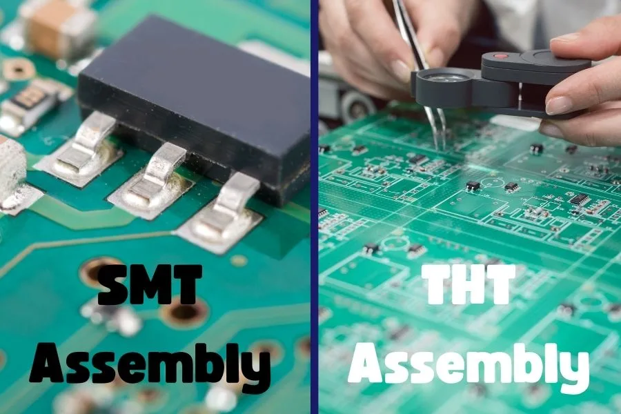
Comparing SMDs vs. THT Components
Another difference worth noting is between surface mount devices and through-hole technology (THT) components.
THT components have metal leads or pins that are inserted through holes drilled in the PCB and soldered on the opposite side. SMDs in contrast are soldered directly onto surface pads without leads passing through holes.
Some key differences between SMDs and THT parts:
- SMDs allow higher component density and miniaturization. THT requires adequate spacing for drilled holes.
- SMDs sit flush on the PCB surface, while THT components are secured through the board.
- SMD assembly can be highly automated. THT often involves more manual soldering.
- Re-working and replacing SMDs is more difficult than swapping out THT components.
- THT provides strong mechanical anchoring. SMDs are more prone to shear stresses.
- SMD prevailing trend as PCBs become more compact. But THT still useful in some applications.
Both SMDs and THT components have roles in PCB manufacturing. Knowing their pros and cons helps select the best approach per design.
| Key Defferences between SMD and THT Components | ||
|---|---|---|
| PCB Components | SMDs | THT components |
| Size | Small | Large |
| Weight | Light | Heavier than SMDs |
| Pins | Very short | Long |
| Fine-pitch | Can be fine-pitch | No |
| Prices | Normal | Lower than SMDs |
| Typical devices | Resistors, capacitors, inductors, ICs | Components for plug needs such as USB |

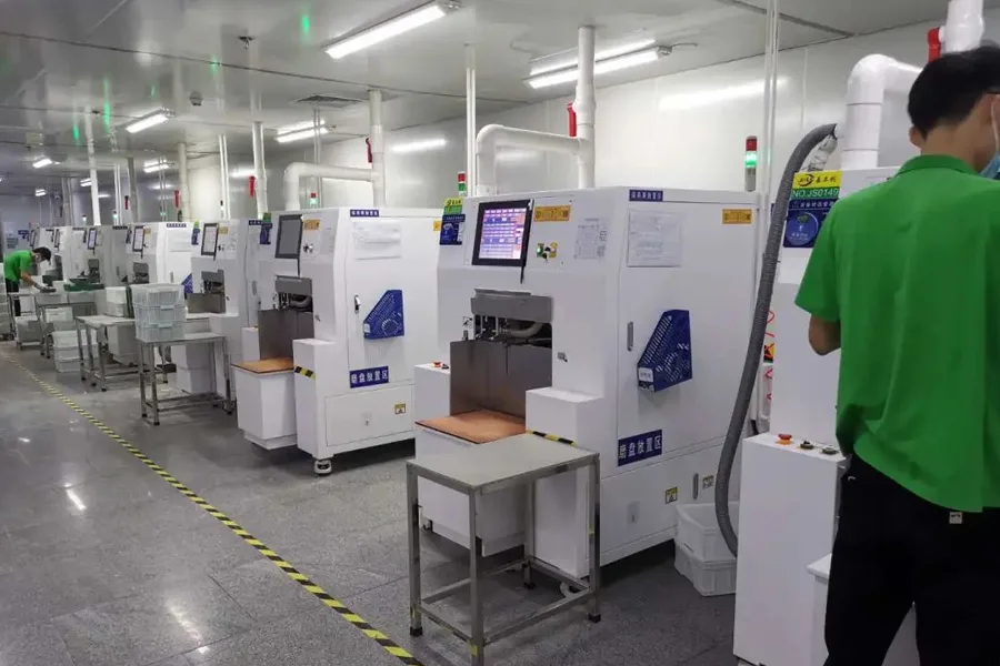
Why Choose JHYPCB for Your SMD and SMT PCB Assembly
With over 15 years of experience, JHY PCB is a leading PCB prototype assembly manufacturer in China. Whether your designs utilize SMD components, THT holes, or complex SMT, JHYPCB can expertly assemble your boards.
Reasons to choose JHYPCB include:
- Massive SMT assembly capacity with numerous SMT lines
- Extensive experience with all types of SMD components and packages
- Competitive pricing and quick turnaround times
- One-stop prototyping from PCB fabrication to complete SMT assembly
- Excellent quality control with multiple inspection stages
- Strong engineering support for assembly optimization
JHYPCB provides the SMT assembly expertise, SMD sourcing, and process quality to bring your innovative designs to life. Contact us today to get started.
Conclusion
In summary, SMT refers to the overall surface mount assembly process, while SMD refers specifically to the electronic components designed for SMT production. Although related, these are distinct terms with unique meanings in PCB manufacturing.
Accurately understanding the differences between SMT and SMD ensures clear communication between teams, avoids purchasing and assembly errors, and facilitates optimized surface mount processes. Keeping SMT and SMD terminology precisely separated matters for efficient, high-quality PCB production.
Related Reading