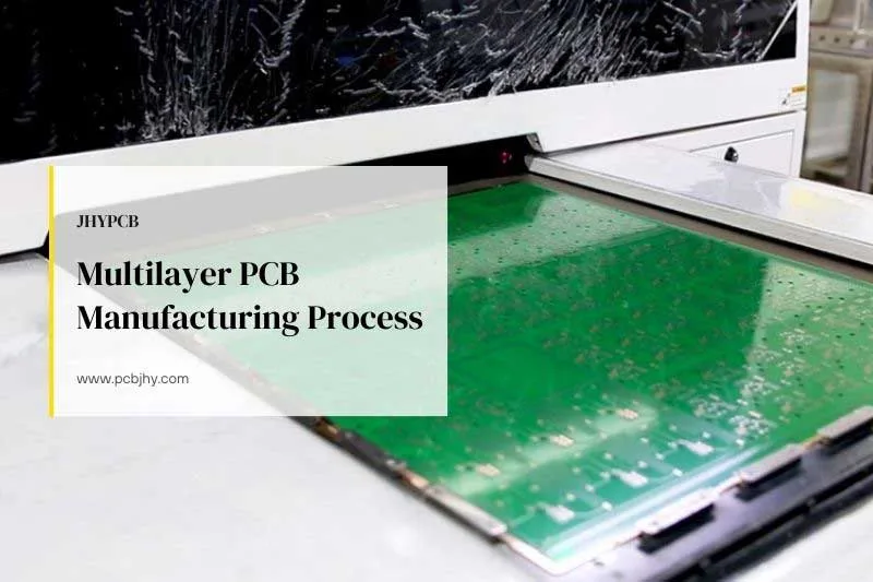
Printed circuit boards are the foundation of electronics, providing the mechanical structure and electrical connections for components in all types of devices and systems. PCBs come in two major varieties – rigid and flexible.
Rigid PCBs use stiff, flat substrate materials like FR4 fiberglass. They provide stability and ease of assembly, making them suitable for products like computers, routers, and set-top boxes.
Flexible PCBs (flex PCBs) use thin, bendable materials like polyimide in the construction. This allows flex PCBs to dynamically flex and conform to space constraints in products like cameras, wearables, and medical devices.
Both rigid and flexible PCBs have their own strengths and weaknesses depending on the application. Rigid PCBs offer higher reliability and thermal performance for complex, high-power designs. Flex PCBs provide compactness and mechanical compliance for size and weight-constrained applications.
When embarking on a new electronics project, one of the early key decisions is choosing between rigid or flexible PCB technology. This article provides a comparative overview of rigid and flex PCBs to help guide the optimal selection based on design requirements and tradeoffs.
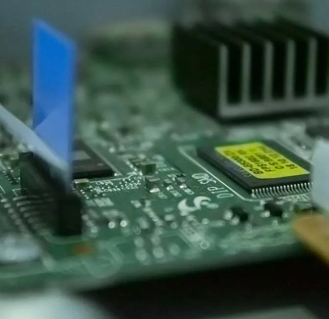
Rigid PCBs: The Backbone of Electronics
Rigid PCBs are composed of flat, inflexible insulating substrates made from materials such as FR-4 fiberglass. This gives rigid PCBs their characteristic stiffness and structural stability.
Rigid PCBs support and interconnect electronic components using conductive copper traces etched from copper foil and plated onto the board substrate. Vias and plated-through holes provide electrical connections between layers in multi-layer rigid PCB designs.
Some of the key advantages of rigid PCB technology include:
- Reliability – The rigid structure prevents warping or flexing that could cause cracks and connection failures. This makes rigid PCBs suitable for long-lifespan products.
- Thermal Performance – The fiberglass laminates used in rigid PCBs conduct heat well, allowing effective heat dissipation from high-power components.
- Layout Flexibility – Rigid PCBs facilitate complex, dense component layouts and intricate routing of traces between components.
- Easy Assembly – The stiff, flat construction provides stability for automated SMT assembly and manual soldering.
- Cost Effectiveness – Established rigid PCB manufacturing processes yield affordable boards in high volumes.
Rigid PCBs are ubiquitous across consumer electronics, industrial equipment, telecommunications devices, and medical systems. However, the rigid nature does impose some limitations on flexible, compact product designs.
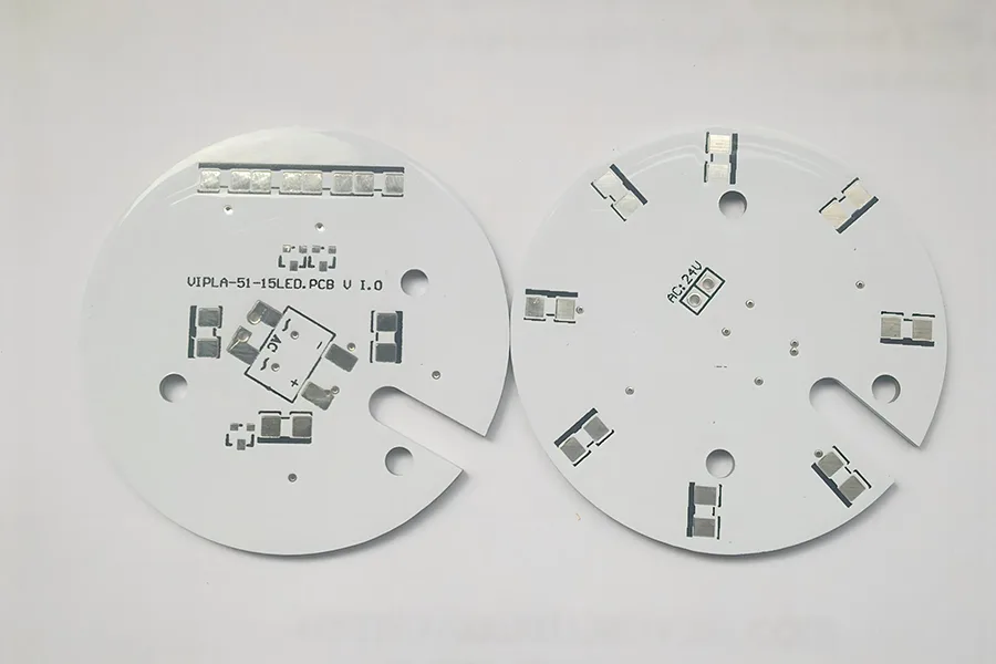
Rigid Printed Circuit Board
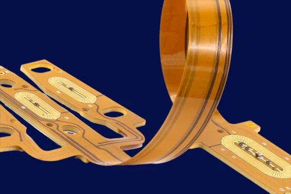
Flexible PCBs: Enabling Compact, Dynamic Designs
Flex PCBs provide electronics the ability to bend, twist, and flex to accommodate unique product designs.
Flex PCB substrates use thin, flexible insulating materials like polyimide instead of rigid fiberglass. Flexible copper traces etched on the substrates maintain conductivity even when bent around tight radii.
Some key benefits of flex PCB technology are:
- Compactness – Flex circuits can tightly integrate with moving components and fold into small spaces. This allows for smaller, lighter system designs.
- Customization – Flexible circuits can be fabricated in customized shapes and configurations as needed by the design.
- Dynamic Flexing – Flex PCBs maintain full functionality under continuous dynamic bending and repeated motion.
- Reliability – Flexible materials withstand vibration, shock, and flexing without cracking or failing.
- Cost Savings – Flex PCBs allow component consolidation by embedding parts into the flexible substrate.
The main disadvantages of flex PCBs are more complex routing and lower current ratings versus rigid PCBs.
Flex PCBs are widely used in consumer wearables, medical devices, robotics, aerospace, and automotive applications where compactness and mechanical compliance are required.
Key Factors in Comparing Rigid and Flex PCBs
When selecting between rigid and flexible PCB technologies for a product, some important factors to compare include:
- Electrical Performance
Rigid PCBs can manage higher current loads and voltage levels compared to flex PCBs. The rigid construction also provides superior insulation resistance. Flex PCBs have lower capacitance for high frequency applications. - Mechanical Properties
Flex PCBs can withstand much higher levels of mechanical flexing, vibration and shocks versus more fragile rigid PCBs. Rigid PCBs offer sturdier structure for assembling heavy components. - Design and Layout
Rigid PCBs allow for high density component placement and trace routing. Flex PCBs enable customized configurations but have more complex trace routing. - Production Costs
For simple designs in high volumes, rigid PCB fabrication has lower costs. But flex PCBs reduce system assembly costs through part consolidation. - Reliability
Rigid PCBs last longer in general operating conditions. But flex PCBs better withstand stresses like shock and vibration.
Carefully weighing these tradeoffs helps determine if rigid or flex PCB technology is optimal for the product requirements and operating environment. Prototyping both options can provide real-world performance data.
Differences in manufacturing materials
Rigid PCBs and flexible PCBs are made of different types of materials, each with its own advantages and disadvantages.
Common materials used for rigid PCBs include:
- FR-4: This is a type of fiberglass-reinforced epoxy laminate material that is widely used for rigid PCBs due to its excellent mechanical strength and thermal stability. FR-4 is also relatively inexpensive, making it a popular choice for mass production.
- Metal Core: Metal core PCBs have a layer of metal, usually aluminum, as the base material instead of fiberglass-reinforced epoxy. They offer excellent thermal conductivity and are used in high-power applications where heat dissipation is critical.
- Ceramic: Ceramic PCBs are made of a ceramic material that offers excellent thermal and electrical properties. They are used in high-frequency and high-temperature applications, such as power electronics and microwave communication.
On the other hand, common materials used for flexible PCBs include:
- Polyimide: This is a type of polymer material that is widely used for flexible PCBs due to its high-temperature resistance and flexibility. Polyimide is also resistant to chemicals and abrasion, making it a popular choice for harsh environments.
- PET: Polyethylene terephthalate (PET) is a type of plastic material that is commonly used for flexible PCBs due to its low cost and ease of processing. PET is also resistant to moisture and can withstand a wide range of temperatures.
- PTFE: Polytetrafluoroethylene (PTFE) is a type of polymer material that is known for its excellent electrical properties and high-temperature resistance. PTFE is commonly used in high-frequency and microwave applications.
In summary, the choice of material for a PCB depends on the specific application requirements, such as mechanical strength, thermal stability, flexibility, and cost.
Differences in the manufacturing process
The manufacturing processes for rigid PCBs and flexible PCBs differ due to the different materials used and the flexibility of the latter. Here is a comparison of the manufacturing processes for rigid PCBs and flexible PCBs:
Manufacturing Process for Rigid PCBs:
- Preparing the substrate: The substrate material, typically FR-4, is cut to the required size and cleaned to remove any impurities.
- Applying the copper layer: A layer of copper is applied to the substrate using either electroplating or a lamination process.
- Etching the copper layer: The unwanted copper is then etched away using a chemical process, leaving behind the desired circuit pattern.
- Drilling the holes: Holes are drilled into the PCB for component placement and electrical connections.
- Applying the solder mask: A layer of solder mask is applied to the PCB to protect the copper traces and facilitate soldering.
- Applying the surface finish: A surface finish, such as gold or silver, is applied to the PCB to improve the solderability and prevent oxidation.
Manufacturing Process for Flexible PCBs:
- Preparing the substrate: The substrate material, typically polyimide, is cut to the required size and shape.
- Applying the copper layer: A layer of copper is applied to the substrate using either electroplating or a lamination process.
- Etching the copper layer: The unwanted copper is then etched away using a chemical process, leaving behind the desired circuit pattern.
- Drilling the holes: Holes are drilled into the PCB for component placement and electrical connections.
- Applying the coverlay: A layer of coverlay, which is a flexible insulating material, is applied to the PCB to protect the copper traces and facilitate soldering.
- Adding stiffeners: Stiffeners, which are made of FR-4 or another rigid material, may be added to the PCB to provide additional support and stability.
Tools and Techniques:
The manufacturing processes for both types of PCBs use similar tools and techniques, including CAD software, CNC machines for drilling and routing, chemical etching, and soldering equipment. However, flexible PCBs require additional tools and techniques to handle the flexible substrate, such as roll-to-roll processing, laser cutting, and flexible solder mask materials.
Differences in Features and Applications
Rigid PCBs and flexible PCBs have their own distinct characteristics and applications. Here is a comparison of their advantages, disadvantages, and suitable applications:
Rigid PCBs:
Advantages:
- High rigidity and durability
- Better thermal conductivity
- Lower cost for mass production
- High mechanical strength and stability
Disadvantages:
- Not flexible, limited bending capability
- High weight and volume
- More prone to mechanical failure due to inflexibility
Suitable Applications:
- Products that require high mechanical strength and stability, such as aerospace and defense equipment, automotive electronics, and industrial control systems.
- Products that do not require bending or flexibility, such as desktop computers, televisions, and audio equipment.
Flexible PCBs:
Advantages:
- Highly flexible and bendable
- Lightweight and thin
- Better resistance to vibration and shock
- Space-saving design, suitable for compact and portable products
Disadvantages:
- Higher cost compared to rigid PCBs
- Lower mechanical strength and durability
- Limited thermal conductivity
Suitable Applications:
- Products that require flexibility, such as wearable devices, flexible displays, and medical devices.
- Products that require lightweight and space-saving designs, such as mobile phones, tablets, and laptops.
- Products that require resistance to vibration and shock, such as automotive electronics and aerospace equipment.
In general, rigid PCBs are more suitable for applications that require high mechanical strength and stability, while flexible PCBs are more suitable for products that require flexibility and space-saving design. When choosing between rigid PCBs and flexible PCBs, designers should consider the specific requirements of the product, such as its size, weight, flexibility, and durability, as well as its intended application and environment.
Differences in Design
When designing a rigid PCB or flexible PCB, there are several limitations and key points to keep in mind:
Limitations for Rigid PCB design:
- The board cannot be bent or flexed.
- The thickness of the board cannot be easily changed once it has been manufactured.
- The board may require additional support to prevent mechanical failure due to its inflexibility.
- The board must be designed to accommodate any required connectors or mounting holes.
Limitations for Flexible PCB design:
- The board should be designed with a minimum bend radius to avoid damaging the circuits.
- The circuit layout and routing must be carefully planned to avoid overstressing the flexing portions of the board.
- The materials used in the board must be selected to withstand repeated flexing without cracking or breaking.
- The board must be designed to accommodate any required connectors or mounting holes.
When selecting the best PCB type for a given application, designers should consider the following factors:
- Mechanical requirements: If the product requires high mechanical strength and stability, a rigid PCB may be the better choice. If the product requires flexibility, a flexible PCB may be more appropriate.
- Environmental conditions: If the product will be exposed to high temperatures, vibration, or shock, a rigid PCB with good thermal conductivity and mechanical stability may be the best option. If the product will be subject to repeated flexing, a flexible PCB with durable, flexible materials may be more suitable.
- Size and weight: If the product needs to be small and lightweight, a flexible PCB may be preferable, as it can be made thinner and more compact than a rigid PCB.
Cost: The cost of manufacturing a flexible PCB is generally higher than that of a rigid PCB, so designers must balance the desired functionality and performance of the product with the available budget.
In summary, the choice between rigid PCB and flexible PCB depends on the specific requirements of the product, including its mechanical requirements, environmental conditions, size and weight, and cost. By carefully considering these factors and adhering to the design limitations and key points of each PCB type, designers can choose the most appropriate PCB type for their application.
Differences in cost and efficiency
The cost and efficiency of rigid PCBs and flexible PCBs vary depending on several factors, including the complexity of the design, the materials used, and the manufacturing process. In general, flexible PCBs tend to be more expensive to manufacture than rigid PCBs due to the additional materials and manufacturing steps required to produce them. However, flexible PCBs can offer cost savings in other areas, such as reducing the need for additional connectors or cables.
When it comes to efficiency, rigid PCBs and flexible PCBs also have their own strengths and weaknesses. Rigid PCBs are typically more efficient when it comes to high-speed signal transmission and power delivery, as their inflexible nature allows for more precise control of signal paths and power traces. Flexible PCBs, on the other hand, are more efficient when it comes to reducing space and weight, as their flexibility allows them to be folded or bent into tight spaces.
To determine which PCB type to choose for a given application, designers should consider the specific requirements of the product and weigh the costs and benefits of each PCB type. If the product requires high-speed signal transmission or power delivery, a rigid PCB may be the most efficient and cost-effective option. If the product needs to be compact and lightweight, a flexible PCB may be the better choice despite its higher manufacturing cost. In cases where both signal transmission and space/weight considerations are important, designers may need to strike a balance between the two and consider using a combination of both rigid and flexible PCBs in the product design.
Ultimately, the decision to choose a rigid PCB or flexible PCB will depend on a variety of factors, including the specific requirements of the product, the available budget, and the desired level of performance and functionality. By carefully considering these factors and weighing the costs and benefits of each PCB type, designers can select the most appropriate option to achieve the best cost-efficiency balance.
Hybrid PCBs: Combining Rigid and Flexible Circuits
For some complex designs, utilizing both rigid and flexible PCB technologies in a hybrid approach combines the best of both worlds.
Hybrid PCBs integrate rigid and flexible circuits together into a single interconnected system. Some common ways hybrid PCBs are implemented include:
- Rigid-Flex – Combining stiff and flexible substrates in a single PCB with flexible “hinges”. Allows bends and folds while maintaining rigid sections.
- Rigid-Flex-Rigid – Multiple rigid PCBs interconnected by flexible circuits that can be folded and bent as needed.
- Flexible Interconnects – Using flex circuits as removable interconnects between multiple rigid PCB assemblies.
- Flexible Jumpers – Short flexible jumper connections to bridge gaps and spaces between components on a rigid PCB.
- Embedded Components – Incorporating components like ICs into the flexible circuit substrate itself.
The benefits of hybrid PCBs include optimizing rigid PCB and flexible PCB strengths in the same design. Rigid portions of hybrid PCBs handle complex connections and high-power components. Flexible portions provide dynamic flexing and 3D configuration.
Hybrid PCBs require upfront planning to effectively integrate the rigid and flex materials and fabrication. When designed well, hybrid PCBs enable small, lightweight and reliable electronic designs not possible with just a single PCB type.
Choosing the Optimal PCB Technology for Your Product
When embarking on a new electronics hardware project, carefully evaluate whether a rigid, flexible, or hybrid PCB design approach best fits your requirements. Here are some tips:
- Clearly identify the key mechanical, electrical, and usage requirements early in the design process. These determine if rigid or flex PCB technology is more suitable.
- Involve PCB designers and manufacturers early for guidance on optimal PCB design strategies based on the product goals. Their expertise is invaluable.
- Build multiple prototypes trying different PCB technologies during development. Evaluate the real-world performance tradeoffs with rigorous testing.
- Consider future maintenance and enhancement plans. Flex PCBs and hybrids allow easier field upgrades and modifications over the product lifetime.
- Analyze the total cost implications. Flex PCBs reduce assembly costs but increase PCB fabrication costs.
- Enlist an experienced, capable PCB manufacturer as your partner. Their capabilities in working with the latest rigid, flex, and hybrid PCB technologies are crucial.
With careful planning and testing, you can select the ideal PCB technology to meet the physical, electrical, and reliability needs of your next big project.
Conclusion
In summary, rigid PCBs and flexible PCBs have distinct differences in terms of their materials, manufacturing processes, features, and applications. Rigid PCBs are inflexible, made of rigid materials, and offer precise control of signal paths and power traces. They are most suitable for high-speed signal transmission and power delivery applications, such as in computers, telecommunication equipment, and medical devices.
Flexible PCBs, on the other hand, are made of flexible materials and can be bent or folded to fit tight spaces. They are ideal for applications where space and weight are critical, such as in wearable devices, aerospace, and automotive electronics.
When choosing between rigid PCBs and flexible PCBs, designers should consider the specific requirements of the product and weigh the costs and benefits of each PCB type. If the product requires precise signal control and power delivery, a rigid PCB is the most suitable option. If space and weight are the primary concerns, a flexible PCB is the better choice.
However, in some cases, the product may require both precise signal control and compact design. In this situation, a hybrid PCB design that combines rigid and flexible PCBs may be the most effective solution.
In conclusion, choosing the right PCB type is crucial to ensure optimal performance, functionality, and cost-effectiveness of the final product. By understanding the differences and applications of rigid PCBs and flexible PCBs, designers can make informed decisions to achieve the best design outcome.
Related Reading