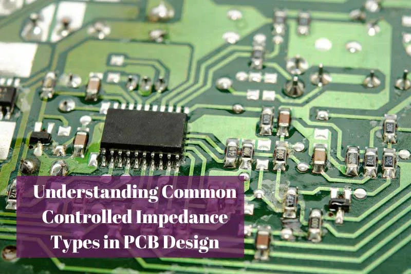
With the ever-increasing speeds and complexity of electronic circuits, controlling impedance on PCBs has become crucial. Many circuits today need to carry high-frequency signals, with speeds up to 5Gbps like USB 3.0. At these high speeds, managing PCB impedance is vital for proper function.
Mismatched impedances can cause signal reflections along a trace as a signal propagates through a PCB. This can degrade signal integrity and in extreme cases, lead to burnt pins. Properly controlling impedance, on the other hand, allows maximizing signal transfer and preventing loss or distortion.
PCB impedance control ensures signals can travel smoothly from source to destination. It involves carefully designing PCB trace widths, thicknesses, and materials to achieve specific impedance targets. Accurate impedance matching enables high-speed signals to transmit with fidelity, avoiding errors and packet loss.
This article will detail how PCB impedance control works. We’ll discuss the basic concepts of impedance and why it’s so important for high-speed PCBs. We’ll also explore specific techniques and methods for controlling impedance. Hopefully, this provides readers with a better understanding of this complex topic.
What is Impedance?
Impedance is like resistance but for alternating currents instead of direct currents. It measures how much opposition a circuit presents to a current that changes direction periodically. Impedance is determined by resistance, which inhibits current flow, and reactance, which arises from inductive and capacitive properties. Reactance impedes current by storing and releasing energy. Together, resistance and reactance make up impedance, measured in ohms like regular resistance.
On a PCB, many factors contribute to impedance along a trace, including the width and height of the trace, the dielectric material separating it from the ground plane, frequency, and trace length. Wider and thicker traces with closely spaced ground planes tend to have lower impedance. Choosing dielectric materials with certain properties also helps control impedance. Managing all these factors allows designers to achieve target impedance values for traces.
Controlling impedance is critical because impedance mismatches cause signal reflection. This distorts and attenuates signals, degrading quality. Impedance control along traces ensures smooth current flow and maximum power transfer for signals at high frequencies. This is crucial for error-free communication between ICs and other components. Proper impedance matching maintains signal integrity through the entire path.
Why Control Impedance?
Controlling impedance is critical for proper high-frequency signal transmission. At frequencies over a few hundred megahertz, any impedance mismatches can cause major reflection issues. This degrades signal quality and makes high-speed communication difficult.
Reflections occur at points of impedance discontinuity. Here the signal is forced to reflect back, colliding with the original signal and causing distortion. In severe cases, reflections lead to data loss and burnt pins.
In contrast, when the source and transmission lines have matched impedances, the signal can propagate smoothly from one point to another without reflections. This allows high-speed signals to transmit with fidelity, carrying information efficiently.
Additionally, controlling impedance optimizes signal transmission efficiency along the PCB. Proper impedance matching transfers maximum signal power. Mismatches result in wasted power as heat.
In summary, carefully controlling PCB impedance is crucial for reliable high-speed communication. It ensures signal integrity, avoiding distortion and data loss. This is essential for high-speed interfaces like USB 3.0.
Methods of Impedance Control
There are several primary methods to design and control impedance on PCBs:
- Careful trace dimensioning – Wider, thicker traces generally have lower impedance. Calculating precise trace sizes can achieve target impedance.
- Choosing suitable dielectric materials – FR-4, Rogers, ceramic, etc. have different dielectric constants that impact impedance. Select materials as needed.
- Using ground/power planes – Reference planes adjacent to signal lines help control impedance. Planes provide capacitive coupling.
- Serpentine trace routing – Slightly adjusting trace paths can fine-tune impedance.
- Back-drilling plated through holes – Reduces parasitic inductance of vias to help control impedance.
- Termination resistors – When perfect impedance matching isn’t possible, termination resistors can help absorb reflections.
- Analog simulations – Modeling and optimizing impedance pre-fabrication using software.
Combining these techniques enables precise impedance control for maintaining the signal integrity of PCB traces.
Impedance Matching
Proper impedance matching is critical for high-speed signals. The goal is to match the source impedance to the transmission line impedance and finally the load impedance. This maximizes signal power transfer and eliminates reflections.
For example, designing a chip’s output impedance to be 50 ohms. The PCB trace is also designed for 50 ohm characteristic impedance. Finally, the lead and input pin receiving the chip is 50 ohms too. This allows the signal to propagate smoothly without reflective errors.
However, perfect matching isn’t always possible. In this case, termination resistors can help absorb reflections. A terminator equal to the line’s characteristic impedance is placed at the end. This absorbs reflected waves and protects the signal.
Another technique is using impedance tuning elements like capacitors and inductors to correct small mismatches. Tuning these passive components can “tune” the impedance for a match.
In summary, carefully designing the source, transmission line, and load impedances to match is key in high-speed PCB layouts. Impedance matching is critical to ensure reliable and intact signal transmission.
Conclusion
In summary, managing PCB impedance is crucial for high-speed digital designs. Impedance determines how signals propagate along the board.
Controlling impedance prevents reflections, signal distortion, and data loss. Careful design of trace geometries and materials achieves impedance targets.
Matching impedances of the source, transmission lines, and load allows smooth signal flow. Termination resistors are used when perfect matching isn’t possible.
By applying proper impedance control techniques, engineers can ensure faithful signal transmission for reliable system operation. This is critical for today’s high-speed digital circuits.
This article provided an overview of basic PCB impedance control principles and techniques. Hopefully, this gives readers useful knowledge on the theory and layout considerations. Grasping this key concept will greatly improve engineering design success.
Related Reading