As a PCB manufacturer, designing and manufacturing high-Tg PCBs is an important part of our business. High Tg PCBs are becoming increasingly popular in the electronics industry due to their ability to withstand high temperatures and provide improved performance and reliability. In this blog post, We will share with you the best practices and tips for High Tg PCB design to ensure the success of your project.
What is High Tg PCB?
High Tg PCB is a type of printed circuit board with a high glass transition temperature (Tg). The Tg is the temperature at which the resin matrix in the PCB starts to soften and lose its mechanical properties. High Tg PCBs are typically made with materials that have a Tg of 170°C or higher, which makes them more resistant to heat, moisture, and mechanical stress.
Importance of High Tg PCB
High Tg PCBs are crucial in applications where the PCB is subjected to high temperatures, such as in automotive, aerospace, and industrial control systems. They are also used in high-density and high-speed PCB designs, where the heat generated by the components can cause the PCB to deform and affect its performance. High Tg PCBs offer better mechanical and thermal stability, which translates to a longer lifespan and better performance for electronic devices.
High Tg PCB Applications
High Tg PCBs are widely used in various industries, including:
Automotive: High Tg PCBs are used in automotive electronic systems that are exposed to high temperatures, humidity, and vibration. These include engine control units, airbag sensors, and infotainment systems.
Aerospace: High Tg PCBs are used in aerospace applications where the PCB must withstand extreme temperatures and mechanical stress. These include avionics, flight control systems, and communication systems.
Industrial control: High Tg PCBs are used in industrial control systems, such as power supplies, inverters, and motor drives.
High Tg PCB Design Guidelines
Designing High Tg PCBs requires careful consideration of several factors, including material selection, board shape, trace and space design, pad and via design, and impedance control.
1. Material Selection
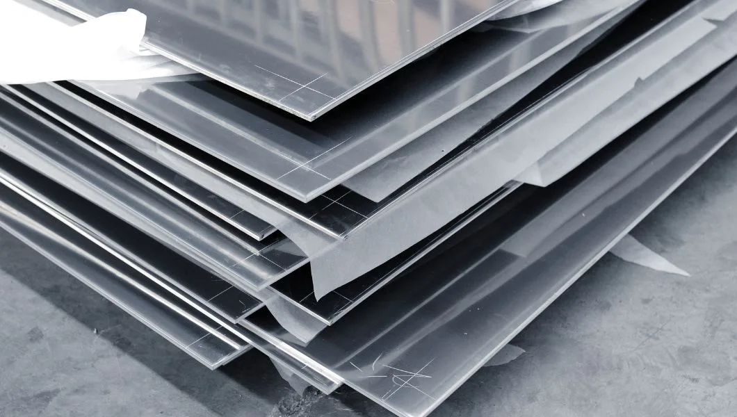
The choice of material is critical in the design of High Tg PCBs. The most common material used in High Tg PCBs is FR-4, which is a composite material made of woven fiberglass cloth and epoxy resin. Other materials such as polyimide and Rogers materials are also used in High Tg PCBs.
- FR-4 with High Tg: FR-4 with High Tg is a popular material choice for High Tg PCBs due to its excellent thermal and electrical properties. The material has a high glass transition temperature, which makes it ideal for applications that require high-temperature resistance.
- Rogers Materials: Rogers materials are a popular choice for High Tg PCBs due to their low loss tangent and excellent electrical properties. The material is also known for its high thermal stability, making it ideal for high-temperature applications.
- Isola Materials: Isola materials are known for their high thermal conductivity, low thermal expansion coefficient, and excellent mechanical properties. The materials are ideal for high-frequency applications and high-temperature environments.
Advanced Learning: Materials Used for High Tg PCBs: A Comparison and Selection Guide
2. Thickness and Layer Count
The thickness and layer count of the PCB should be carefully considered to ensure the mechanical and thermal stability of the board. High Tg PCBs typically have a thickness of 1.6mm to 3.2mm, and a layer count of 4 to 12 layers.
3. Board Shape and Size Limitations
The shape and size of the board are also critical factors in High Tg PCB design. The board shape should be kept as simple as possible to reduce stress on the board. The size of the board should be limited to avoid excessive thermal expansion.
4. Trace and Space Design
The trace and space design should be optimized to ensure that the board can withstand the thermal and mechanical stress of the application. The trace width and spacing should be carefully calculated to achieve the desired impedance and minimize signal loss.
5. Pad and Via Design
The pad and via design should also be optimized to ensure good electrical and mechanical performance. The pad size and shape should be chosen to provide a strong mechanical connection between the component and the board. The via size and placement should be optimized to ensure good electrical performance and avoid thermal stress.
Impedance control is critical in High Tg PCB design, especially in high-speed and high-frequency applications. The impedance of the traces should be carefully calculated and controlled to minimize signal loss and ensure good electrical performance.
Conclusion
High Tg PCB design requires careful consideration of the materials, board shape, trace and space design, pad and via design, and impedance control. The manufacturing process for High Tg PCBs is similar to that of regular PCBs, but the materials and process parameters used are optimized for High Tg PCBs. Electrical and mechanical testing, as well as quality control, are critical to ensuring that the board meets the required specifications and quality standards. By following the best practices and tips outlined in this article, PCB designers can ensure the success of their High Tg PCB projects.
Related Reading