Welcome to the JHYPCB tech blog! As a leading printed circuit board manufacturer in China, we receive many questions about the differences between high-speed and high-frequency PCBs. While both boards are designed to support faster electric signals, they serve unique applications and have important distinctions.
In this article, we’ll provide an in-depth look at high-speed and high-frequency PCBs, including:
- What defines each type of board
- Key applications and markets
- Major design considerations like impedance control and materials
- How high-speed PCBs differ from high-frequency PCBs
- Guidance on when to use each technology
- JHYPCB’s capabilities and expertise
Whether you are designing cutting-edge servers and network devices or next-generation wireless and radar systems, understanding high-speed and high-frequency PCB technologies is crucial. Keep reading as we explore these two essential board types in detail!
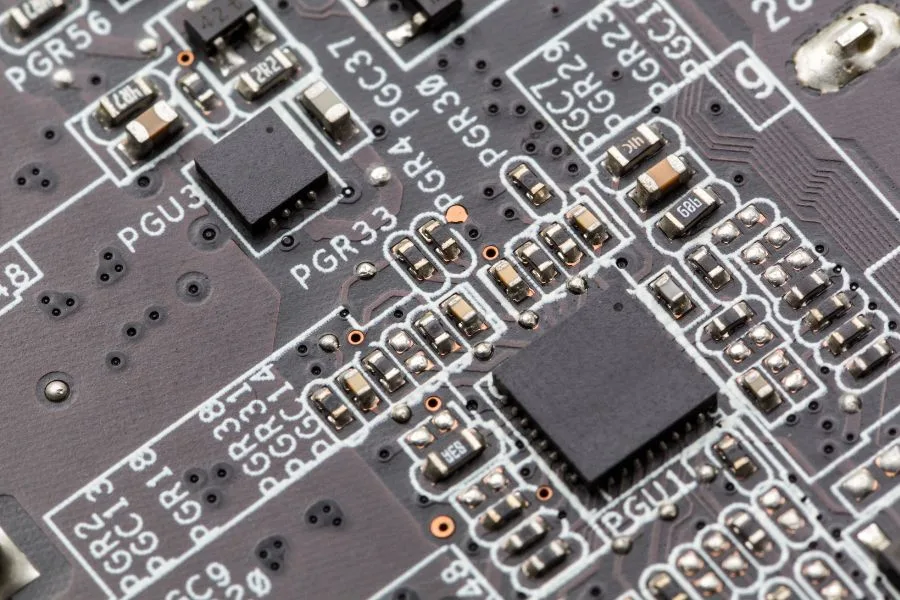
What are High Speed PCBs?
High-speed PCBs are designed to support fast digital signals for applications like routers, switches, servers, and other computing devices. As operating speeds have increased from MHz to GHz rates, PCB designers face challenges related to signal integrity and maintaining clear 1s and 0s. High-speed signals have very fast rise and fall times, which requires attention to impedance control, layer stackup, trace dimensions, and dielectric materials.
Key design concerns for high-speed PCBs include:
- Impedance control – traces must have a controlled impedance, typically 50Ω or 75Ω, to prevent unwanted reflections. This is achieved through trace width/spacing and reference planes.
- Layer stackup – layer materials and arrangements must be optimized for speed, considering aspects like skin effect and dielectric properties. High-speed signals require wider traces and dielectric materials like FR-4.
- Trace width/spacing – traces must be wide enough to control impedance but spaced far enough apart to minimize crosstalk between signals. High-density routing requirements must be balanced.
- Materials – FR-4 is commonly used for its availability and cost, but other materials like polyimides may be used for better performance. Dielectrics with consistent properties are key.
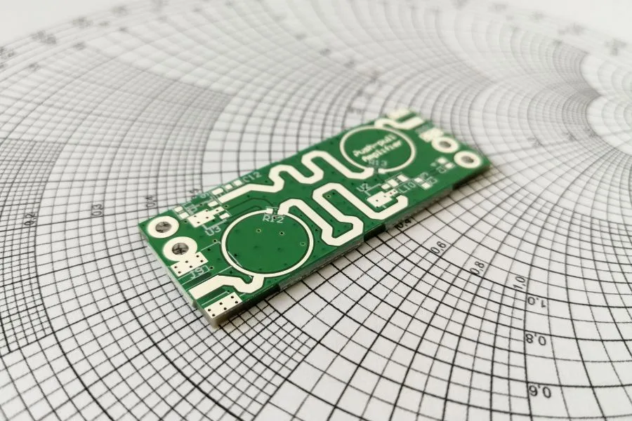
What are High Frequency PCBs?
High-frequency PCBs are designed for analog high-frequency signals in applications like radio frequency (RF) circuits, radars, satellites, 5G networks, and more. These boards must handle signals with frequencies in the microwave and gigahertz range. Key design concerns include controlled impedance, low-loss PCB materials, shielding, and managing parasitics.
Some specific considerations for high-frequency PCB design include:
- Controlled impedance – Maintaining a 50Ω impedance match is crucial for minimizing signal reflections in the RF signal path. This requires proper trace width/spacing.
- Low-loss materials – Materials like Rogers RO4000 or Taconic TLY minimize dielectric and conductor losses at high frequencies. FR-4 has too high of a loss.
- Shielding – Shielding cages or ground planes prevents radiation and coupling between circuits. Attention to grounding is important.
- Managing parasitics – Parasitic capacitance and inductance must be minimized through proper component placement and routing techniques. Vias can affect parasitics.
- Testing – Extensive modeling and prototype testing is done to verify the design works correctly at the intended operating frequencies. Issues like resonances must be avoided.
Key Differences Between High Speed and High Frequency PCB
There are several key differences between high-speed PCBs and high-frequency PCBs:
- Signal types – High-speed PCBs handle fast digital signals for computing applications. High-frequency boards are designed for analog RF/microwave signals.
- Speed vs. frequency – For high-speed PCBs, the focus is on fast rise and fall times, expressed as speed. For high-frequency boards, the key metric is the operating frequency.
- Materials – High-speed PCBs typically use conventional FR-4, chosen for its widespread availability and lower cost. High-frequency boards require specialized RF laminates like Rogers or Taconic to achieve the needed performance.
- Loss – At high frequencies, radiation, and dielectric/conductor losses are a major concern. High-frequency boards require attention to impedance, parasitics, and other losses. High-speed boards focus less on minimizing loss.
- Shielding – Shielding and isolation between circuits is critical for high-frequency PCBs to prevent interference and crosstalk. This is less of a concern for high-speed digital boards.
- Termination – Proper termination of traces with resistive networks is needed on high-speed PCBs to prevent reflections. Less termination is required on high-frequency boards.
Design Considerations
There are several important design considerations for both high-speed and high-frequency PCBs:
Impedance control – Both PCB types require careful control of trace impedance but use different approaches. High-speed PCBs use reference planes and calculate trace width/spacing. High-frequency boards use width/spacing and may taper traces.
Layer stackup – A well-planned layer stackup is crucial for both. High-speed boards focus on trace routing and minimizing crosstalk. High-frequency boards also minimize dielectric thickness and carefully plan component placement.
SI/PI analysis – Modeling signal and power integrity is important to predict performance. Both use SI/PI analysis, but high frequency requires additional modeling of effects like parasitic resonances.
Materials – High-speed uses FR-4 for cost reasons but may use other dielectrics for better performance. High frequency requires specialized RF laminates. Both must use consistent dielectric materials.
Terminations – High-speed PCBs focus more on proper terminations to prevent signal reflections. Terminations are less common on high-frequency boards.
Manufacturing – Both board types require tight process controls and testing. High-frequency PCBs use processes to minimize surface roughness and tightly control dielectric thickness.
In summary, both PCBs share common design principles but implement them in different ways optimized for their operating frequencies and applications. Careful planning is required for either board to function correctly.
Conclusion
In conclusion, high-speed and high-frequency PCBs are important but distinct electronics industry applications. Both enable faster and more complex designs, but high-speed boards are focused on fast digital signals, while high-frequency boards handle sensitive RF/analog signals up to microwave frequencies. Key differences include operating frequencies, materials used, design concerns around interference and loss, and termination techniques.
While the constraints differ, both types of boards require careful engineering and planning around impedance control, stackup, SI/PI, manufacturability, and testing. At JHYPCB, we have extensive experience with various PCB technologies and applications. Our engineering team can provide the right design and manufacturing solutions, whether your project requires a high-speed digital board or an advanced RF/microwave board requiring specialized materials and processes.
With our advanced manufacturing capabilities and turnkey PCB services, JHYPCB is ready to be your high-speed and high-frequency PCB partner. Please contact us to discuss your next project and how we can help bring your product vision to life.