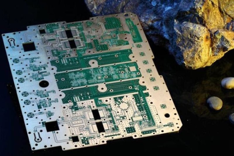
High frequency printed circuit board is a specialized type of PCB designed to transmit high-frequency signals. These types of PCBs have higher performance standards, such as low loss, impedance matching, and stability, making the selection of PCB materials critical to achieving the desired electrical performance. This article will guide you in selecting suitable materials for your high-frequency PCB design and provide information about JHYPCB’s services.
Impact of Materials on High Frequency PCB Performance
High-frequency signals have unique transmission characteristics and requirements that must be considered when designing high-frequency PCBs. These signals are typically measured in gigahertz (GHz) and require fast transmission with minimal losses. High-frequency PCB designs often require tight tolerances for trace widths, via sizes, and component placement to ensure consistent signal quality.
The choice of material is critical in achieving the desired electrical performance for high-frequency PCBs. The dielectric constant (Dk) determines how much capacitance is present between layers and affects the characteristic impedance of the circuit. Lower Dk values result in higher characteristic impedance, while higher Dk values result in lower characteristic impedance.
Another important parameter is the loss tangent (tan δ), which characterizes the energy lost as heat due to internal friction within the material. A low-loss tangent material is preferred for high-frequency applications because it increases the circuit’s Q or quality factor and exhibits low signal attenuation.
In addition to these parameters, other factors such as thermal expansion coefficient, moisture absorption rate, and cost must also be considered when selecting appropriate materials for high-frequency PCB design. For example, materials with a low thermal expansion coefficient help to minimize stress and distortion during temperature changes. Materials with low moisture absorption rates are preferred because water can affect the electrical properties of the material, leading to signal degradation.
Furthermore, the role played by materials in signal transmission should not be overlooked. In high-frequency circuits, signals propagate along the surface of conductors. Therefore, the physical properties of the materials used in the PCB, including surface roughness and conductor thickness, directly impact signal performance. Signal reflection can occur at the interfaces between different materials, causing signal distortion. Therefore, selecting compatible materials with similar electrical and mechanical properties is essential to achieving high performance in high-frequency PCB designs.
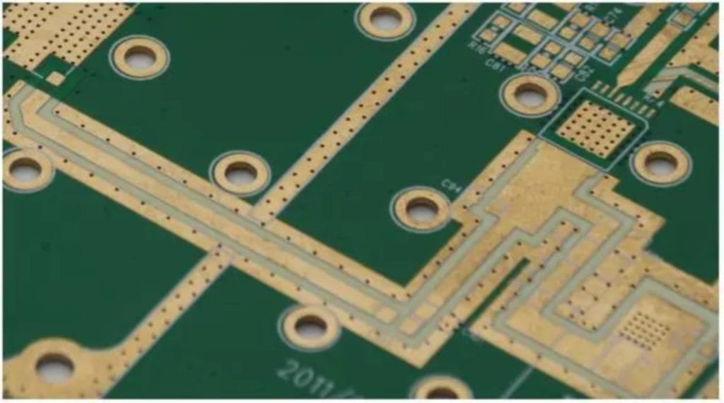
Common Types of High Frequency PCB Materials
Choosing the right material for a high-frequency PCB is crucial to achieving optimal performance. This section will introduce several common types of high-frequency PCB materials, including their properties and applications.
FR-4: FR-4 is a widely used PCB material due to its low cost and good mechanical properties. However, it has a relatively high dielectric constant (around 4.5) and loss tangent (around 0.02), which makes it less suitable for high-frequency applications. It can be used in low-frequency circuits or as a substrate material for higher-frequency designs, but its use in high-frequency applications is limited.
PTFE-based materials: These materials, such as Teflon, have a low dielectric constant (around 2.2-2.4) and a very low loss tangent (around 0.0005). They are ideal for high-frequency applications because they exhibit low signal attenuation and high Q factors. PTFE materials are also compatible with various circuit designs and can be used in multilayer designs. However, they are more expensive than FR-4 and can be difficult to process due to their low thermal conductivity.
RF Polyurethane-based materials: RF Polyurethanes are relatively new materials specifically designed for high-frequency applications. They have a low dielectric constant (around 2.5) and a low loss tangent (around 0.003), making them suitable for frequencies up to 40 GHz. They also have good thermal stability, allowing them to maintain their performance under temperature changes. However, they are more expensive than FR-4 and PTFE materials.
Other materials: In addition to the above materials, other options are available for high-frequency PCBs, including ceramic-filled materials, liquid crystal polymer (LCP), and Rogers Corporation’s RO4000 series. These materials offer unique properties, such as high thermal conductivity or a low coefficient of thermal expansion, but they are generally more expensive and have limited availability.
In conclusion, selecting the appropriate material for a high-frequency PCB depends on various factors, including the desired frequency range, circuit design, and cost considerations. By understanding the properties and applications of common high-frequency PCB materials, designers can make informed decisions to achieve optimal performance for their designs.
Key Factors to Consider When Selecting High Frequency PCB Materials
Choosing the right material for a high-frequency PCB is critical to achieving optimal performance. This section will discuss several key factors when selecting high-frequency PCB materials.
Signal speed and operating frequency: The speed and operating frequency are the most important factors to consider when selecting PCB materials. Higher frequency signals require materials with lower dielectric constants and low-loss tangents to minimize signal attenuation and maintain signal integrity.
PCB thickness and layer count: A PCB’s thickness and layer count also affect its electrical performance. For example, a thinner PCB can improve impedance matching, while a thicker PCB can provide better thermal management. Similarly, a PCB with fewer layers can exhibit lower losses than a multilayer PCB design.
The need to reduce losses and improve performance: Another factor to consider is the need to reduce and improve performance. This can be achieved by selecting materials with lower Dk values, lower loss tangents, and higher glass transition temperatures. By reducing losses, designers can improve the signal-to-noise ratio and achieve better overall performance.
Cost considerations: Cost is an important factor when selecting high-frequency PCB materials. PTFE-based materials, for example, offer excellent electrical properties but are more expensive than FR-4. RF Polyurethane materials are also more expensive than FR-4 but can perform better at higher frequencies.
It is important to balance all of these factors to select the appropriate material for a high-frequency PCB. Designers must weigh the required electrical performance, the desired frequency range, and the cost constraints to make informed decisions about material selection. By selecting the appropriate materials, designers can ensure that their high-frequency PCBs meet performance requirements and operate optimally.
How to Choose the Right High Frequency PCB Material
Choosing the right high frequency PCB material is a critical factor in achieving optimal performance. In this section, we will discuss how to choose the appropriate material for your design by comparing different materials’ advantages and disadvantages, comparing parameters like dielectric constant and thermal expansion coefficient, and considering technical and cost factors.
Comparing different high frequency PCB materials: There are several types of high frequency PCB materials available, each with its unique properties. For example, FR-4 is a low-cost material with good mechanical properties but has high dielectric constants and loss tangents, making it less suitable for high frequency applications. PTFE-based materials offer excellent electrical properties, but they can be expensive and difficult to process. RF Polyurethane materials provide good performance up to 40 GHz but are also more expensive than FR-4. By comparing the pros and cons of these materials, you can determine which best suits your application.
Comparing key parameters: The dielectric constant (Dk), loss tangent (tan δ), and thermal expansion coefficient (CTE) are essential parameters that affect the electrical performance of high frequency PCBs. Lower Dk values result in higher characteristic impedance, while lower loss tangents result in lower signal attenuation. A lower CTE helps reduce stress-induced during temperature changes. By comparing these parameters, you can determine which material would best suit your requirements.
Considering technical and cost factors: Technical and cost factors must also be considered when selecting high frequency PCB materials. Technical factors include the compatibility of the selected material with your design, processing costs, and the expected lifespan of the final product. Cost considerations may include the overall cost of the material, quality control testing, and the availability of the material.
In conclusion, choosing the right high frequency PCB material depends on several factors, such as its electrical properties, compatibility with the circuit design, processing cost, and availability. By comparing different materials’ pros and cons, evaluating key parameters, and considering technical and cost factors, designers can select the appropriate high frequency PCB material for their requirements.
Comparison and Explanation of Performance Parameters
When selecting high-frequency PCB materials, several performance parameters must be considered. This section will compare and explain some of the most crucial parameters affecting high-frequency PCB performance.
Dielectric constant: Dielectric constant (Dk) is the ratio of a material’s permittivity to that of free space. It determines how much capacitance exists between conductors and affects signal propagation speed. Lower Dk values result in higher characteristic impedance, while higher Dk values lead to lower characteristic impedance.
Loss tangent: Loss tangent (tan δ) characterizes the energy lost as heat due to internal friction within the material. Materials with low-loss tangents are preferred for high-frequency applications because they exhibit low signal attenuation.
Thermal expansion coefficient: The thermal expansion coefficient (CTE) measures how much a material expands or contracts due to temperature changes. Materials with low CTE values help minimize stress and distortion caused by temperature variations.
Glass transition temperature: Glass transition temperature (Tg) is the temperature at which a material transitions from a rigid state to a more flexible state. This parameter is important because it affects the material’s mechanical properties and electrical performance.
Moisture absorption rate: The moisture absorption rate measures how much water a material absorbs when exposed to humid conditions. Moisture can affect the electrical properties of high-frequency PCB materials, leading to signal degradation.
Cost: Finally, the cost is an essential factor when selecting high-frequency PCB materials. PTFE-based materials offer excellent electrical properties but are more expensive than FR-4. RF Polyurethane materials are also more expensive than FR-4 but perform better at higher frequencies.
In conclusion, selecting the appropriate material for a high-frequency PCB requires careful consideration of several performance parameters. By comparing and understanding these parameters, designers can make informed decisions to achieve optimal high-frequency PCB performance.
Precautions for choosing the number of PCB layers and board thickness
When designing a high-frequency PCB, selecting the appropriate layer count and thickness is essential to achieving optimal performance. This section will discuss some key considerations when selecting layer count and thickness.
Layer count: High-frequency circuits generally require fewer layers than low-frequency circuits to minimize signal losses due to traversing through intermediate layers. Reducing the number of layers can help to reduce signal attenuation and maintain signal integrity. However, using less than four layers in a high-frequency design is not recommended because additional layers provide better power and ground planes, which can improve noise reduction.
Thickness: The thickness of a PCB affects the characteristic impedance of microstrip lines. A thinner substrate produces a higher characteristic impedance, while a thicker substrate causes a lower characteristic impedance. As such, selecting an appropriate thickness is critical to matching impedance. Materials with lower dielectric constants are preferred for high-frequency designs to achieve smaller trace widths and better accuracy in controlling impedance.
Specific guidelines: It is recommended to provide specific guidelines for layer count and thickness in the design specifications or requirements to ensure they meet the necessary electrical performance. The guidelines should consider the desired frequency range, signal speed, and other critical parameters.
In conclusion, when selecting layer count and thickness for high-frequency PCBs, it’s important to consider the desired frequency range, signal speed, and other critical parameters. Fewer layers may be preferred to minimize signal losses, while appropriate thickness is critical to ensuring proper impedance matching. The design specifications or requirements should provide specific guidelines for layer count and thickness to ensure they meet the necessary electrical performance.
Customizing High Frequency PCBs with JHYPCB's Services
JHYPCB offers various services to support customers’ high-frequency PCB design needs. This section will discuss how JHYPCB can help you customize your high-frequency PCB design.
Multiple high-frequency PCB material options: JHYPCB provides multiple high-frequency PCB material options such as FR-4, PTFE-based materials (Teflon, Rogers 4350B, Nelco N4000-13), RF Polyurethane materials (Rogers RO4003C, Isola IS680), ceramic-filled materials, and liquid crystal polymer (LCP). This wide range of options enables customers to select the best materials for their design.
Different types of high-frequency PCB fabrication processes: JHYPCB offers different types of high-frequency PCB fabrication processes such as multilayer stack-up, blind buried via, impedance control, coplanar waveguide (CPW), and microstrip line designs. These processes enable customers to customize their designs based on their unique requirements.
Material procurement service: JHYPCB also offers material procurement service, where customers can rely on JHYPCB’s sourcing expertise to obtain the right high-frequency PCB material required for their design.
Rich experience and professional knowledge: With years of experience in providing high-quality PCB design and manufacturing services, JHYPCB has accumulated rich experience and professional knowledge that can provide valuable insights and suggestions to customers. This expertise can help customers make informed decisions when customizing their high-frequency PCB design.
In conclusion, JHYPCB offers various services to help customers customize their high-frequency PCB designs. These services include multiple high-frequency PCB material options, different types of high-frequency PCB fabrication processes, material procurement services, and expert advice. Customers can achieve optimal high-frequency PCB performance by leveraging JHYPCB’s experience and expertise.
Conclusion
In conclusion, designing and fabricating high-frequency PCBs requires careful consideration of several critical factors. Such factors include choosing the appropriate material, selecting the right layer count and thickness, simulating and testing the design’s performance, and customizing the PCB according to specific requirements.
High-frequency PCBs are essential in many applications that require fast signal transmission, low noise, and reliable performance. Therefore, designing and manufacturing them correctly is crucial to avoid costly errors and ensure optimal performance.
JHYPCB offers services and expertise to support customers’ high-frequency PCB design needs. By leveraging JHYPCB’s experience and knowledge, customers can confidently customize their designs, knowing they will achieve the desired level of performance.
Overall, by considering all the necessary factors throughout the design process and utilizing the available resources, customers can ensure their high-frequency PCBs meet all the required specifications, resulting in long-term reliability and functionality.

