When signals travel across a PCB, they flow through conductive traces much like water flows through pipes. The signals encounter resistance, slowing them down and potentially causing reflections or distortions if the trace impedance isn’t properly matched to the devices. Impedance is like the resistance to flow that the signal experiences. Many factors affect the impedance on a PCB including the width and thickness of traces, the materials used, and how closely spaced the traces are to each other or ground planes. Controlling impedance is crucial for clean and reliable signal transmission across a circuit board. Matching impedance values allows the signals to transfer efficiently without bouncing back and getting distorted. As PCB designers, understanding what impacts impedance equips us to optimize our boards for signal integrity. This helps prevent issues like timing problems, logic errors, and electromagnetic interference. In this article, we will explore the key factors that determine impedance on printed circuit boards.
What are Impedance Controlled PCBs?
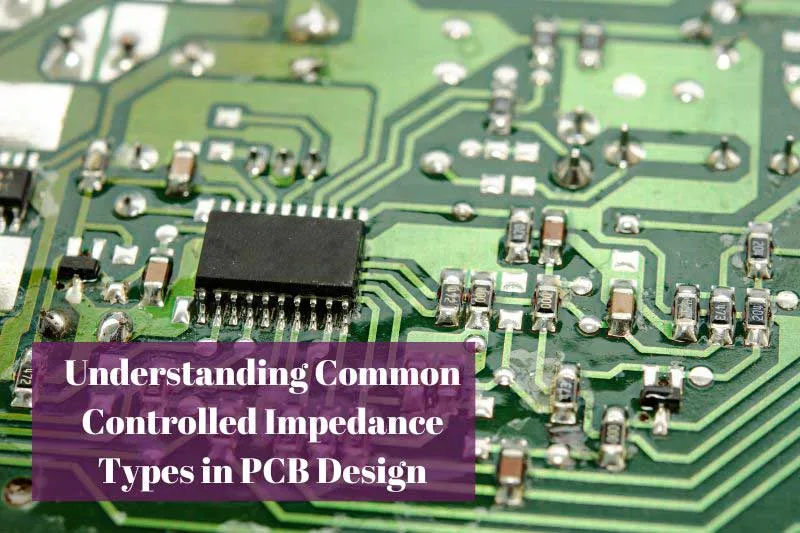
Impedance controlled PCBs are designed to control the impedance of the signals that are transmitted through the PCB. Impedance is the measure of the opposition that a circuit presents to the flow of current when a voltage is applied. PCBs that are not impedance controlled can lead to signal distortion, which can result in degraded signal quality and ultimately, the malfunctioning of electronic devices.
Impedance controlled PCBs are designed to ensure that the impedance of the signals transmitted through the PCB is consistent and matched to the desired value. This is achieved by carefully controlling the width, thickness, and spacing of the conductive traces on the PCB.
Factors affecting PCB impedance
Impedance is a complex property of a circuit that several factors can influence. This article will explain impedance factors, including trace width and thickness, dielectric constant, and the distance between traces, via placement, temperature, and frequency.
- Trace Width
The width of copper traces is one of the biggest factors controlling impedance. Narrower traces lead to higher impedance because the signals are more constrained, like pinching a hose to restrict water flow. Wider traces have lower impedance, allowing signals to propagate with less resistance like a wide pipe. Wider lines also allow more current since there is more cross-sectional copper area. Impedance is inversely proportional to trace width. Wider traces reduce resistance and capacitive coupling, lowering impedance. - Trace Thickness
Thicker copper traces have lower impedance compared to thinner ones. A thicker trace is like a wider pipe – it lets signals pass with less resistance. Thinner traces are more constraining like kinking a hose, increasing impedance. The skin effect also comes into play, where at higher frequencies current travels near the trace surface. A thicker trace gives more skin area to reduce AC resistance. More copper depth equals lower impedance. - Dielectric Material
The dielectric substrate material separating traces has a major effect on impedance. FR-4 fiberglass with resin is the standard – it has a dielectric constant of around 4.5. Materials like ceramics or Teflon have much lower constants near 3, reducing capacitance between traces and lowering impedance. Dielectrics with lower constants insulate signals better since less energy leaks between traces. The weave style and resin content in FR-4 also impact impedance slightly. - Trace Spacing
The distance between traces and planes affects coupling. Tighter spacing increases capacitive coupling, which helps lower impedance by providing a return path. Wider spacing reduces coupling, increasing impedance. Closer ground planes also help control impedance by strengthening the return current path. - Number of Layers
More PCB layers allow wider trace widths since routing space is increased. This lowers impedance by reducing resistance and capacitance. Shorter routes are also possible with more layers, helping control impedance. Fewer layers require thinner, higher impedance traces. - Frequency
The frequency of signals affects impedance since materials interact differently at higher frequencies. Skin effect becomes significant, altering current flow toward the trace surface. Impedance should be modeled over the entire frequency range of operation. - Component Density
Higher component density brings traces closer together, increasing capacitive coupling to the ground which lowers impedance. Sparsely populated boards can have higher impedance with less coupling. Component placement should balance density with impedance control. - Plane Layers
Using continuous reference planes like unbroken ground or power layers helps control impedance. Planes provide low inductance return paths for signals which helps maintain consistent impedance along a trace. Plans also reduce cross-talk by isolating signals. Stitched planes or voids in planes can cause impedance discontinuities. - Trace Length
The length of traces impacts impedance. Longer traces have higher resistance and inductance, increasing impedance. Matching trace lengths controls impedance since different lengths will have different impedance values. This is important for signals like clocks or differential pairs. Even small differences in trace length can skew timing or unbalanced signals. - Vias
Vias act as inductors, adding impedance along a trace. Each via can add around 0.5-0.7 nH of inductance. Too many vias in a line will cause impedance discontinuities. When possible, route layer changes to minimize vias to maintain consistent impedance. For differential pairs, match via counts to balance impedance. - Terminations
Proper trace terminations are needed to absorb signals and prevent reflections that disturb impedance. Common termination methods are series resistors or AC-coupled caps to the ground. Terminations should match trace impedance. Improper termination leads to reflections and ringing that corrupt signal integrity. - Modeling
Use modeling software to simulate how a PCB stackup and routing will perform at relevant frequencies. This verifies trace dimensions and spacings to provide the right impedance before manufacturing PCBs. Modeling helps optimize impedance control as the design progresses.
Conclusion
Controlling impedance on printed circuit boards is crucial for the proper functioning of circuits. The width and thickness of copper traces, the dielectric material properties, layer stackups, plane configurations, and component layout all impact the impedance seen by signals. Wider, thicker traces with close spacing to ground planes result in lower impedance, while thinner, narrower traces spaced farther from planes increase impedance. By tuning the physical and material characteristics of the PCB, designers can engineer controlled impedance traces that match the impedance of ICs and other components in the system. This impedance matching prevents unwanted reflections and distortions that degrade signal integrity. Carefully modeling the PCB stackup and layout is key to optimizing impedance control and ensuring signals transmit clearly across the board. With an understanding of the factors that influence impedance, PCB designers can make choices that result in boards with clean signals, stable timing, and reliable functionality.