


Your Trusted Prototype PCB Manufacturing And Assembly Partner.
When you partner with us, we do everything to ensure your PCB manufacturing and assembly are completed on time to your specifications with the highest quality.
Leading manufacturer of PCB Fabrication and Assembly in China.
When it comes to PCB design, testing is an integral step in the process. Design engineers need to ensure that the testing process for the PCB is efficient while also minimizing the cost of testing. To achieve this goal, design engineers must consider the feasibility of testing before the design process begins. Design for Testability (DFT) is a design methodology that enhances the testing efficiency of a PCB by considering the testing requirements.
DFT can help design engineers identify and correct potential testing issues earlier in the design process, thus avoiding repetitive manufacturing, testing, and alterations later on. The three key optimizations that DFT aims to achieve are:
Therefore, considering DFT is critical in the PCB design process. In the following sections, we will introduce some methods and strategies of DFT to improve the testing process, reduce testing costs, and enhance product quality.
Designing for Testability in PCB Design guidelines is an essential aspect of modern electronic design. In this section, we will discuss the fundamental concepts related to DFT in more detail.
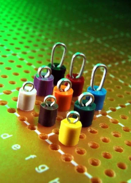
Test points are locations on a printed circuit board where tests can be performed to verify the functionality of the components. These points are typically marked with test pins or test holes that correspond to the components they are testing. The number and location of test points should be carefully considered during the design process to ensure that all necessary components can be tested efficiently.
Test pins are specialized pins on a PCB that are designed to carry test signals. They are typically longer than normal pins and have special features such as test pads or header contacts that allow them to support test equipment. Test pins are used to connect test equipment to the components being tested, allowing for easy and accurate testing.
Test holes are small openings in the PCB that are used to hold test equipment such as probes or meters. They are typically located near the edges of the component being tested, with the test equipment inserted through the hole to perform the test. Test holes should be carefully placed to avoid interfering with other components or causing damage during testing.
SMD (Surface Mount Device) components are those that are mounted directly on the surface of the PCB using adhesive or mechanical means. These components are typically smaller in size and have a higher density than traditional through-hole components, making them more difficult to test. However, careful design and layout can help minimize the impact of DFT on SMD components.
To achieve more comprehensive testing, adding test points to the PCB design is crucial. Test points are places on the PCB where test equipment can be connected to measure various signals and debug the circuit. By including well-placed test points in the PCB design, engineers can easily access the circuit and test its performance.
When adding test points, it is important to consider where they should be placed. Test points should be placed in locations that allow easy access to critical signals, such as power and ground, and to components of interest. The placement of test points should also consider the type of testing that will be done, such as functional testing or boundary-scan testing.
To ensure that test points are aligned with the final objectives of the PCB design, it is important to involve the testing team in the design process early on. This can help identify critical areas that require testing and determine the best locations for test points. Additionally, an iterative design process that involves ongoing communication between the design and testing teams can help refine the placement of test points based on feedback from testing results.
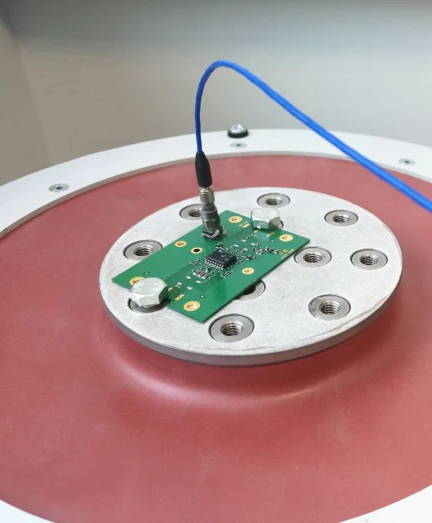
Electronic testing and functional testing are two distinct types of testing that are used to verify the functionality and quality of PCB designs.
Electronic testing focuses on verifying the electrical characteristics of the PCB, such as checking for shorts and opens, measuring impedance, and validating signal integrity. This is typically done using specialized equipment such as oscilloscopes, signal generators, and spectrum analyzers.
On the other hand, functional testing is performed to verify the overall functionality of the PCB. This involves testing the PCB in a real-world environment to ensure that it can perform all the intended functions correctly. This may include verifying the various inputs and outputs of the PCB and checking for any potential errors or issues.
To execute these tests during the PCB design and manufacturing process, a comprehensive test strategy must be developed. This strategy will typically include a combination of electronic testing and functional testing to ensure that the PCB is thoroughly tested and meets all necessary quality standards.
In terms of the testing process, electronic testing is usually performed early in the design process, typically during the prototyping phase. During this phase, the PCB design is verified for electrical issues using specialized testing equipment.
Functional testing, on the other hand, is typically performed later in the design process, after the PCB has been manufactured and assembled. During this phase, the PCB is tested in a real-world environment to verify its overall functionality and to ensure that it can perform all the intended functions correctly.
One limitation of electronic testing is that it only verifies the electrical characteristics of the PCB and does not necessarily guarantee that the PCB can perform all of its intended functions. Functional testing, on the other hand, provides a more comprehensive testing approach that can verify the overall functionality of the PCB.
However, functional testing can be more time-consuming and costly than electronic testing, as it requires the PCB to be tested in a real-world environment. Additionally, functional testing may not be able to detect all problems or issues with the PCB, as some issues may only become apparent during extended use or under specific conditions.
Ultimately, the choice between electronic testing and functional testing will depend on the specific requirements and quality standards of the PCB design. A comprehensive test strategy that includes both types of testing can help to ensure that the PCB is thoroughly tested and meets all necessary quality standards.
Designing for Testability in PCB Design guidelines are essential to ensure that electronic components can be tested accurately and efficiently. In this section, we will discuss the key considerations that must be taken into account during the PCB design process to achieve successful DFT results. From avoiding blind areas to ensuring maintainability and signal integrity, these factors play a critical role in ensuring that components can be tested with confidence. By following these guidelines, designers can create PCBs that meet the highest standards of testability and reliability, ultimately leading to better product performance and customer satisfaction.
Avoiding Blind Area:
Blind area refers to any part of the PCB that is not connected to any other part of the board. These areas can create problems during DFT as they can cause signal reflections, interference, and other issues that can affect test accuracy. To avoid blind areas, designers should use layer stack configurations and routing techniques to connect all parts of the board. This can include using vias or other methods to connect different layers or sub-circuits.
Ensuring Connectivity:
Connectivity refers to the ability of components on the PCB to communicate with each other and with external devices such as test equipment. During DFT, it is essential that all components have sufficient connectivity to ensure accurate testing results. Designers should carefully consider the number and location of interconnect points between components, as well as the type of interconnect used (such as wires, pads, or headers).
Maintaining Maintainability:
Maintainability refers to the ease with which components can be repaired or replaced if necessary. During DFT, it is important to design PCBs with maintainability in mind. This can include using standard component packages that are easy to remove and replace, ensuring that components have clear labels and markings, and using through-hole components where possible to make repairs easier.
Improving Signal Integrity:
Signal integrity refers to the quality and reliability of signals transmitted over the PCB. During DFT, it is important to design PCBs with good signal integrity in mind. This can include using proper routing techniques to minimize signal reflections and interference, using high-quality dielectric materials to reduce signal attenuation, and ensuring that all components are placed correctly to avoid signal corruption.
Testing is a critical part of modern PCB design, and there are several benefits and advantages to incorporating it in the design process:
Testing can detect several issues in a circuit board, including:
Therefore, testing plays a crucial role in PCB design, not only improving product quality and reliability, but also helping designers reduce costs and increase production efficiency.
Incorporating DFT into the PCB design process requires careful consideration of several factors such as test coverage, test points, and test equipment. Below are some strategies and methods that can be used to implement DFT into PCB design:
Designing with Testability in Mind
Designing with testability in mind involves identifying potential testability issues and minimizing them during the design process. This requires an understanding of potential test coverage issues as well as test equipment capabilities. For example, the designer may need to add more test points to the design or adjust component placement to improve the accessibility of test points.
Implementing Built-In Self-Test (BIST)
Built-In Self-Test (BIST) is a technique in which a device under test (DUT) is designed to test itself. This approach can help to reduce the number of external test equipment required, reducing costs and test time. BIST can be implemented through various means such as logic built into the device or through external hardware.
Boundary-Scan Testing
Boundary-Scan Testing is a technique that allows for testing of individual components within a PCB. This approach involves adding boundary-scan cells to a PCB design which allow for the capture and testing of signals. Boundary-scan testing can help to identify issues such as incorrect pin assignments or open/short circuits.
Design for Fault Isolation
Designing for Fault Isolation involves designing the PCB in such a way that faults can be quickly identified and isolated. This can be achieved through various means such as the use of test points, fault identification circuits, or fault segregation.
In PCB design, the relationship between layout and DFT is crucial to ensure that the board can be tested thoroughly and accurately. To achieve this, several key factors need to be considered during the design process.
Firstly, it is important to avoid over-crowded wiring, as this can make it difficult to insert test probes or probes may even damage adjacent components or traces. One way to avoid over-crowding is through layered design, such as power layers, ground planes, and signal layers. This allows for easier routing and better isolation of different types of signals, which in turn helps to ensure that testing can be performed effectively.
Furthermore, it is important to maintain connectivity between different layers. This can be achieved through techniques such as via stitching or ground stitching, to ensure proper grounding and to reduce noise. Additionally, filling blind areas with vias or other techniques can help make sure that signal paths are uninterrupted and that the signals can reach the test points without interference.
Another important consideration is the use of rule spacing and minimum spacing to control the width and spacing of traces. This can help to reduce the impact of EMI and crosstalk – common problems that can arise during testing. By designing to these minimum spacing requirements, designers can help to mitigate the effects of noise and interference.
Overall, a good layout with DFT in mind can help to improve the reliability of the product, reduce testing time, and minimize potential problems. By careful design with good layout practices, designers can help to engineer PCBs that are both easy to test and reliable.
The layout of surface mount device components has a significant impact on the design for test in PCB design. Proximity issues between components must be avoided to ensure that there is enough space for testing and repair. A proper amount of distance must be maintained between components using multi-layered designs and rules for spacing. Electrical connections between components can be established using test pins, but their position must be chosen carefully to avoid interfering with the normal operation of the components. Test holes can be employed for mechanical connections or to provide additional anchoring; however, they should not be positioned in such a way as to affect the normal operation of the components or result in false readings. Additionally, electrical connections or anchoring between components can be achieved using the solder pads of SMD components, provided that they are positioned in a way that does not affect the normal operation of the components or result in false readings.
DFT is an important aspect of PCB design as it allows for efficient and effective testing of the board’s functionality. Through the use of various DFT strategies, such as layout techniques for SMD components, testing pin usage, and testing via implementation, designers can ensure the testability and comprehensive testing of the PCB.
In conclusion, DFT plays a critical role in ensuring the quality and reliability of a PCB design. It is essential that designers implement DFT strategies throughout the design process to ensure that the board can be tested fully and efficiently.
When you partner with us, we do everything to ensure your PCB manufacturing and assembly are completed on time to your specifications with the highest quality.
Fill out the form below, and we will get back to you within the next 24
hours to complete the order, and then you’re all set to get started!